PID looptime: why it is not only about frequency
Last 18 months was an extremely good period of time for all mini-quad enthusiasts. Progress, hardware and software both, was just incredible. Who could have guessed that in less than 2 years mini-quads will evolve into main group of drones with such excellent flight characteristics. Just take a look at looptime. When I entered the hobby, standard looptime was 3500us (285Hz). Then, someone noticed that mini-quads fly much better when looptime is lowered and it started. Right now, standard looptime is 2000us (500Hz), while Betaflight starts with 1000us (1kHz) or even 500us (2kHz) in case of faster flight controllers.
Just by looking at numbers one might come to a conclusion, that looptime should be kept as low as possible and higher control loop frequency is better. Hey, 2kHz should be twice as good as 1kHz, right? One might even thing that it's really about frequency. Well, this is both false and true: sometimes it is not about frequency, sometimes it is about frequency after all.
When it's not about frequency
Difference might be small, but very important: it is not important how often PID control loop can change output (change motor rotation speed)! It is important how fast after a change happened PID controller can start to react by changing actuator's (propeller rotation speed) output. Get it?
Unfortunately, there is only one simple method to minimize control loop delay: to perform it as often as possible. This is why looptime 2000us is better than 3500us and 1000us is better than 2000us. Probably 500us is better than 1000us too. There are 2 catches here:
- control loop delay is not the only delay flight controller is facing
- motor-propeller combo is not not "perfect" device and it can not change it's rotation speed as fast as flight controller might request it. Laws of physics stays in place after all
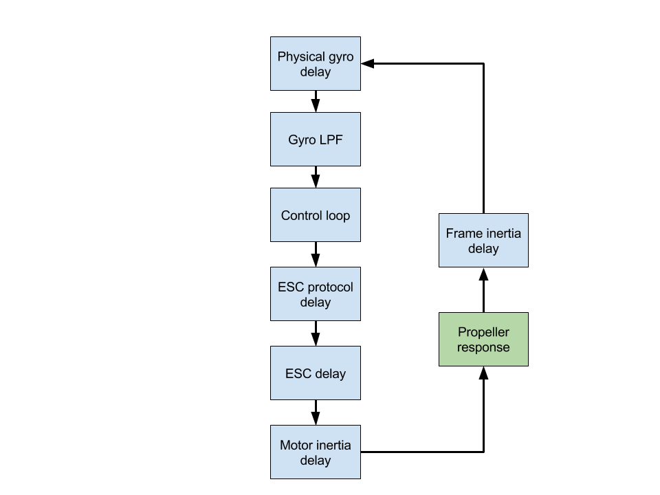
There are several delays in drone control loop force feedback:
| Gyro bandwidth | Delay |
|---|---|
| 256Hz | 0.98ms |
| 188Hz | 1.98ms |
| 98Hz | 2.8ms |
| 42Hz | 4.8ms |
| 20Hz | 8.3ms |
| 10Hz | 13.4ms |
| 5Hz | 18.6ms |
- Gyro physical delay: period of time between rotation begins and gyro can measure it. It is very small and we can ignore it
- Gyro has several settings of digital low pass filter that determine amount of noise that can get through it. Popular MPU6050 has parameters like in a table above. The better filtering the bigger delay. Cleanflight default 42Hz gives 4.8ms delay. It is not an mistake! 4.8ms. 4800us. Almost 2.5 time more that standard 2000us looptime.
- Then comes the looptime itself. 2ms (worse case scenario, 0.1ms on average) by default in CF
- Then, when we have a data that should be sent to ESC, there is an ESC protocol delay. Starting from 2ms in case of PWM, ending at 25us in case of Multishot. Default in Cleanflight is 2ms
- It takes time for ESC to process data and start feeding motor with correct current. Hard to measure it exactly, but with standard 22kHz PWM frequency it is at least 45us. Probably more
- Now motor has to change its rotation speed. Let's skip it since I have no idea how to measure it after all
- Finally, whole drone has some inertia, it takes time and energy to get it moving. Once again, let's ignore it
So, with default values of Cleanflight, measurable delay is 8.8ms (4.8ms gyro + 2ms PID loop + 2ms PWM protocol). What happens when we cut PID looptime in half to 1ms? Delay is lowered to 7.8ms. But wait, what instead of that we lower ESC protocol latency from 2ms to 0.25ms of OneShot125? It's only 7.05ms. We gained more by changing ESC protocol than by lowering looptime from 2000us to 1000us!
That's not all. Imagine a 5" propeller rotating at 18000 RPM (rather hight RPM). At this speed, propellers tip has a liner velocity of almost 120m/s. That is more than third of speed of sound.
And now, 1ms later, we want to cut it's speed by, let's say 10%, because this is what PID controller computed. Is this even possible?
Let's do the math. In 1/1000s we want to cut velocity from 120m/s to 108m/s. That gives 12m/s / 1/1000s = 12000 m/s^2 = 1223g. One thousand two hundred twenty three earth gravities of deceleration! Khem... no way this is physically possible! And that was looptime of 1kHz. With 2kHz it would be almost 2500 gravities. Motor can start to change it's velocity, but can not reach target so fast!
So, there is a limit of control loop frequency. While it makes sense to lower it from 3500us to 2000us. Even from 2000us to 1000us, but gain in terms of flight performance might be very small, if any.
As long as control loop frequency is is kept at reasonable level (in case of mini-quads somewhere around 1kHz), more flight performance improvement will come from lowering gyro signal delay, filters and PID tuning than from increasing this frequency.
When it's frequency after all
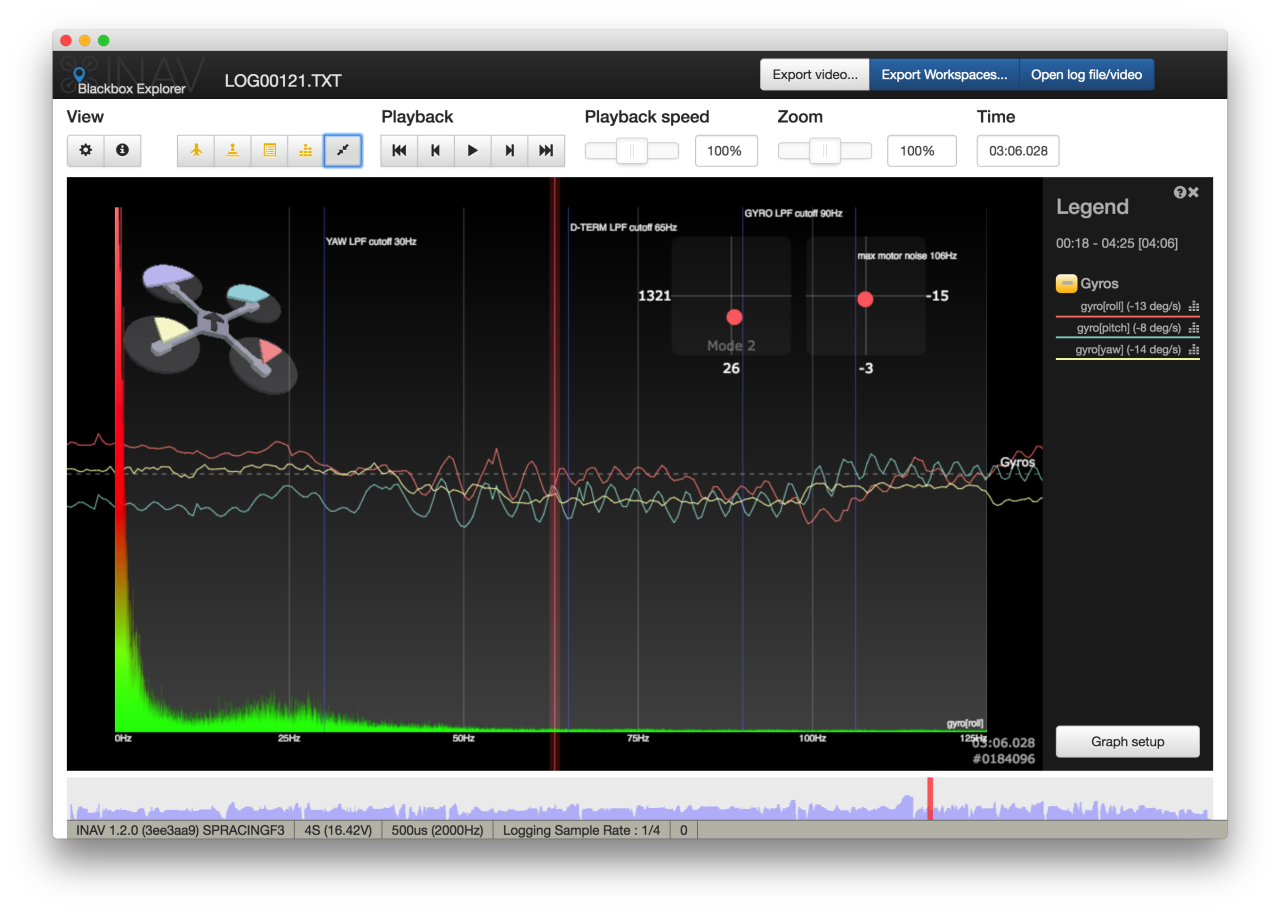
When flight controller reads data from gyroscope, it performs something that is called "sampling". It samples rotation rates measured gyro. Rotation rate in time has to be understood as set of different frequencies. Some of those frequencies comes from rotation of UAV body, some are motor noise, some are bearings noise and so on. Maximum range of frequencies that will be sampled from gyro depends on gyro low pass filter cutoff frequency settings. And we know, that we want as high cutoff frequency as possible (lowest delay as possible). Unfortunately, here comes into play something called Nyquist frequency. Long story short, we can accurately measure frequencies that are lower than half of sampling frequency. So, with a looptime 3500us (285Hz) we can measure only frequencies up to 142.5Hz).
| Looptime | Control loop frequency | Nyquist frequency |
|---|---|---|
| 3500us | 285Hz | 142.500Hz |
| 2000us | 500Hz | 250Hz |
| 1000us | 1kHz | 500Hz |
| 500us | 2kHz | 1kHz |
| 250us | 4kHz | 2kHz |
| 125us | 8kHz | 4kHz |
What happens if there is a frequency higher that Nyquist frequency in a signal we measure? Here comes to play something called aliasing. Aliasing is something nasty. It makes frequencies that we can not measure (above Nyquist frequency) appear in a sampled signal as different frequencies.
With sampling rate 500Hz (Nyquist frequency 250Hz) signal of 270Hz would appear as a 230Hz signal. To make things worse, 770Hz signal would also appear in 230Hz range
You already know that we want to keep delay as low as possible, so gyro DLPF should have cutoff frequency as high as possible. Let's look at our MPU6050. Highest possible setting is bandwidth of 256Hz. Can we sample this signal at 285Hz (looptime 3500) without aliasing? No way. Even 500Hz (2000us) is slightly not enough. In theory, 512Hz would be sufficient. The problem is, that filters are not perfect. Bandwidth of 256Hz does not mean that frequencies above 256Hz would not be present is sampled signal. It only means, that they would be attenuated, weaker, but still there. Strong enough signal much higher than cutoff would still be visible due to aliasing.
Not only that. Also internal, software, low pass filters are not perfect. To give best results they need as many samples as possible.
This is why we want as high gyro sampling frequency as possible. To get rid of aliasing and give software low pass filters the best data possible.
By your powers combined, I am Asynchronous Processing
After reading this longish post one can see two conflicting findings:
- It does not make much sense to increase control loop frequency above 1kHz
- It makes sense to increase gyro sampling frequency as high as possible
The simplest solution would we just to run full control loop as fast as possible and leave output as it is, but this would be huge waste of computational resources.
This is why, Betaflight (and soon INAV but in a slightly different way) allows for independent gyro and PID processing. Gyro is sampled and processed as fast as hardware allows (depends on CPU type and gyro bus: SPI vs. I2C) but PID control loop is executed every n-th execution.
With this approach both sides are happy: no aliasing and we are not wasting CPU to compute data motors can not consume.

I'm Paweł Spychalski and I do things. Mainly software development, FPV drones and amateur cinematography. Here are my YouTube channels:


