-
Cleanflight 1.12 is coming to town...
Looks like Cleanflight release cycle is speeding up. Last stable version, 1.11.0, was published in the beginning of December 2015, next stable release, 1.12, can appear any day now. Its Release Candidate is available for testing for more than a week now.
So, what can we expect? First of all, bad news: no improved GPS navigation from iNavFlight yet. iNavFlight is not ready and looks like it's too big to fit all targets, specially F1 processors. So, we will have to wait a while for it. In the meantime, iNavFlight 1.0 RC4 is ready for testing. And it is very promissing. I've been able to do only a few test flights on it before winter, but results were very nice.
In Cleanflight 1.12.0 we can expect few quite important new features:
- Looptime sync to gyro readouts. This is something that Betaflight users knows very well. No more looptime as we know it. Control loop processes data as soon as it have it from gyros. Approximately every 1000us, since gyro updates with 1kHz frequency. But, that does not mean that we all will be using looptime of 1000. Not all hardware targets with features like GPS have enough computing performance to handle that. This is why CLI command
gyro_sync_denomhas been introduced. It tells CF every which gyro update control loop should be executed. Value of 1 results of looptime around 1000us, value of 2 give looptime of 2000us and so on. Important note: by default gyro sync is disabled and CLIset gyro_sync=ONcommand has to be executed to enable it. - Improved task scheduler. Task scheduler in revious versions of Cleanflight was rather simple. This new implementation will allow for better processing of pheripherials like GPS. Users probably will not see much (if any) difference, but this is required for future features like better GPS navigation,
In addition to that: faster computations and better gyro filtering, bugfixes, documentation updates (to which I contributed too) and smaller improvements. See release notes for full list.
Read more... - Looptime sync to gyro readouts. This is something that Betaflight users knows very well. No more looptime as we know it. Control loop processes data as soon as it have it from gyros. Approximately every 1000us, since gyro updates with 1kHz frequency. But, that does not mean that we all will be using looptime of 1000. Not all hardware targets with features like GPS have enough computing performance to handle that. This is why CLI command
-
Programming ATtiny85 and ATtiny45 with Arduino IDE
What is ATtiny
ATtiny is a fimily of microcontrollers by Atmel, the same company that provides ATmega series used widely in "real" Arduinos. Comparing to ATmega, ATtinys are much simpler, smaller (usually), with less features. But also cheaper, easier to connect, using less energy, and trust me, in many many cases you do not need 32kB of flash memory. If, for example, you want to build a device that will beep every 10 minutes which microcontroller would you use: huge DIP-28 ATmega328P from Arduino UNO R3 or small DIP-8 ATtiny25 that ususes way less power and costs around 1EUR? I would use ATtiny.
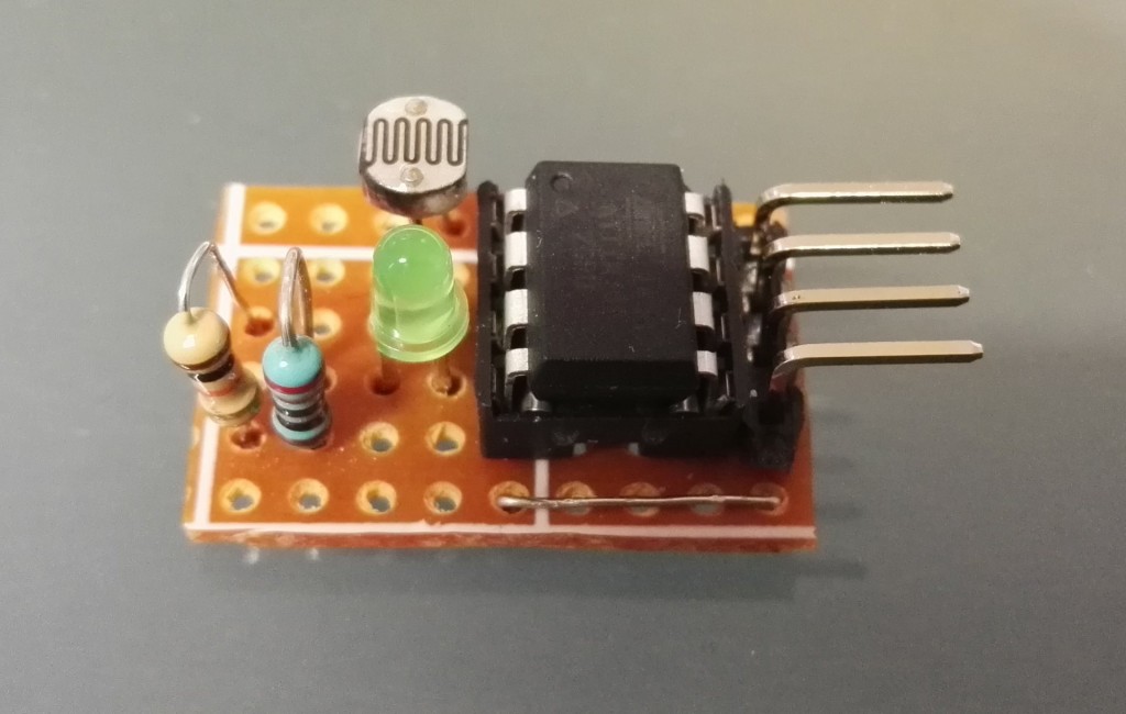
There are many microcontrollers in ATtiny family. In this tutorial and all future in this series I will concentrate on ATtiny85 with 8kB of flash memory. There are 2 simpler versions of it: ATtiny25 and ATtiny45 with respectively 2kB and 4kB of flash, but price difference between them is so small, that I see no point of trying to use them. When buoght from China, it might be even possible to buy ATtiny85 cheaper than its smaller brothers. Read more...
-
Quick review: Gemfan 5x3 (5030) 3 leaf propellers
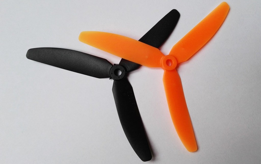
This will be very quick review with a simple conclusion: I will never buy Gemfan 5030 3 leaf propellers again. Never. Why? They are cheap, you can buy them for around $3 for 2 pairs from China. But they have few flaws:
- Every crash, even gentle means at least one broken propeller,
- Quality is low,
- Look at this picture:
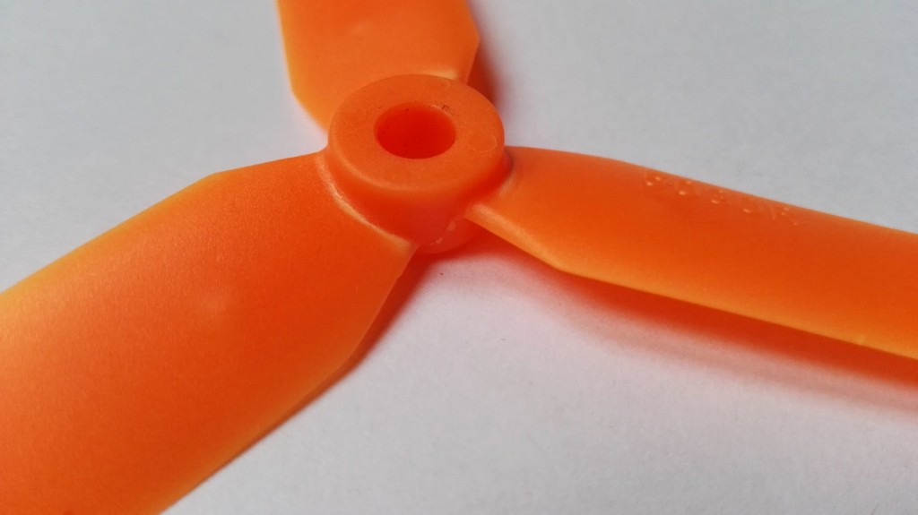 This propeller never hit anything in its life. See white stress marks near hub? They appeared during normal flight. This prop would break soon,
 - At least twice in last 2 months Gemfan 5030 3 leaf broke in flight. In both cases during quite normal flight. No crazy stuff. Simple turn.
So, my verdict is: no, never again. I'm going back to Gemfan 5030 2 leaf version. They are cheaper and offer very similar performance. And I think they are slightly harder to break after all.
Read more... -
Read RC PWM signal with Arduino
Arduinos are cheap and simple development board. You can do a lot with even the simplest of them. For example build you own quadcopter and flight controller (after all MultiWii = Arduino + MPU6050). Of course, this is not as simple as one might imagine and there are few (actually a lot) obstacles that needs to be overcomed. One of them, and very basic, is how to read RC PWM signal provided by radio receiver.
Signal to decode
RC PWM signal passed from radio receiver to servos, ESC, flight controllers is encoded with a length of pulse. Pulse length of 1000us (micro seconds) is minimum stick position and pulse of 2000us length is maximum stick position. Pulses repeat every 20ms for standard 50Hz refresh rate. Like this:
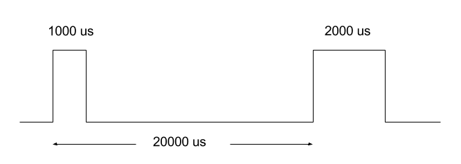
So far, nothing fancy. Read more...
-
Cleanflight software low pass filters
Back in version 1.9, Cleanflight introduced new software low pass filters for gyro readouts, P term and D term of PID controller. They are designed to smooth control loop output and filter gyro inputs from undesired high frequency noise. Unfortunately, Cleanflight documentation was not yet updated and says very little about them. Here are few things that I was able to find out about them.
gyro_cut_hz
This low pass filter (LPF) is a software filter for gyroscope readouts. Most probably the less useful from software LPF filters in Cleanflight. Why? It duplicates (sits on top) of hardware gyro_lpf LPF filter build into MPU6050 or other gyroscope used in flight controller. The only advantage of gyro_cut_hz is a possibility to set any frequency while gyro_lpf accepts only limited set of frequencies. Can be left at 0 (disabled) unless there is a good reason to use it.
To enable it and set cutoff frequency to, for example, 64Hz, enter CLI mode and type:
set gyro_cut_hz=64
savepterm_cut_hz
This LPF is slightly more useful than gyro_cut_hz since P term of PID controller depends on both gyro readout (filtered by hardware gyro_lpf) and user input. So, in some cases P term frequency can be higher than gyro trace. On the other hand, frequency change is so small, that gain from using pterm_cut_hz is minimal. Setting it below gyro_lpf or gyro_cut_hz will make PID control loop react slower than expected and decrease flight performance. Can be left at 0 (disabled) unless there is a good reason to use it.
To enable it and set cutoff frequency to, for example, 32Hz, enter CLI mode and type:
set pterm_cut_hz=64
savedterm_cut_hz
Finally something useful! D term of PID controller, since it is trying to look into a future, can be a source of huge noise and vibrations. After all, looking into a future is always a tricky business. This is why D term and change with totally different frequency than gyro input and there is a very good reason to limit D term change. Too see how excess D noise can affect gyro traces take a look at my Blackbox tutorial.
Limit how much? I have no idea, since it all depends on a machine PID controller is trying to stabilize. Betaflight (Cleanflight fork aiming at 250 and smaller racers) sets it at 42Hz. My personal experience with big and prone to vibration Reptile 500 frame ended at dterm_cut_hz at 14Hz. Rule of thumb is: smaller and more rigid frames allows for higher D term cutoff frequency and 42Hz is a good place to start. Bigger frames might require lower cutoff frequency and 10Hz is lower boundary. On the other hand, I was using dterm_cut_hz at 16Hz on a 250 quad and was happy with results.
To enable it and set cutoff frequency to, for example, 16Hz, enter CLI mode and type:
set dterm_cut_hz=64
saveThis entry is outdated, please refer to June 2016 update
Read more... -
Note on Arduino Uno servo jitter
Yesterday I discovered very nasty feature of Arduino Uno (and all other AVR ATMega328 boards) when using servos. Although official Servo library states that it can support up to 12 servos on Arduino Uno (more on advanced boards as Mega), it does not say much about quality of PWM signal.
Since all connected servos (in case of Arduino Uno/ATMega328) are driven using the same timer (timer1), the more servos are connected, the more jitter is introduced to PWM signal. Control "window" of each servo starts to overlap. This results in a situation when real pulse width jumps up and down, sometimes even outside allowed values.
My experiments says that Servo library can support up to 3 servos per 16 bit timer with acceptable jitter level to use as RC control signal. Specially when PWM signal is fed to flight controller. With 3 channels signal quality was acceptable after enabling input filtering on Cleanflight. 2 PWM/Servo channels did not required input filtering.
4 or more PWM channels can be used when real servos, not flight controller inputs, are used. Servo inertia "solves" issue of signal jitter.
Read more... -
Detecting Cleanflight PID tuning issues with Blackbox: not enough P
This is third part of Cleanflight PID tuning tutorial with Blackbox. Previously I've showed examples of:
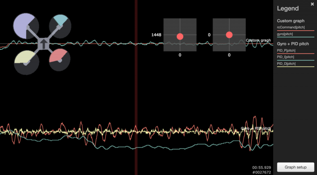
This time it is time for something slightly different: not enough P gain. Usually this problem can be identified without any log analysis. Symptoms are quite visible: multirotor is sluggish during maneuvers, has a tendency to change attitude on its own, constant course corrections are required. In worse cases, it is unflyable. But how does it look like on Blackbox logs.
First of all, symptoms are not so clearly visible. There are no huge oscillations for example. Zoomed out log might event look good on a first glance. For example like this:
-
Detecting Cleanflight PID tuning issues with Blackbox: excess D gain
Welcome to second part of Blackbox PID tuning tutorial. Last time I have showed few examples how excess P gain might look like. Today I will write few words about next common PID tuning problem: too much D. Derivative (future) part of PID controller is very useful, since it allows to smoothen control loop output when it is reaching the target. So, at the end of move (roll, pitch, yaw, anything else) multicopter will start to "slow down" before target is reached. It's just like accelerator pedal in a car. When you want to reach 50 you start to release it before you reach 50, and not in the exact moment you reached target speed. If you would, you would have to use brake to slow down to 50. Derivative part helps not to overshoot. Without it, movement would be shaky, not smooth.
Unfortunately, D is tricky. Like everything that tries to see the future, it is unreliable and can introduce noise. We do not like noise. Not enough D = shaky, mechanical, movement and overshooting. Too much D = extra noise, vibrations, damped response.
How excess D would look like in Blackbox logs? Like this:
-
Quick Peek: Eachine Light-2D Brushless Gimbal
You can buy almost everything from China. Including 2 axis gimbal for less than 50 Euro. Websites like BangGood and Aliexpress sell them worldwide. The only question is: are they any good? I've decided to check that out and I have purchased Eachine Light-2D Brushless Gimbal w/Motor&Controller For DJI Phantom. Of course, it is not only for Phantom. If you can mount it on your multicopter, you can use it. Why not, it is a clone of BaseCam SimpleBGC 8-bit. The most general purpose gimbal controller there is!
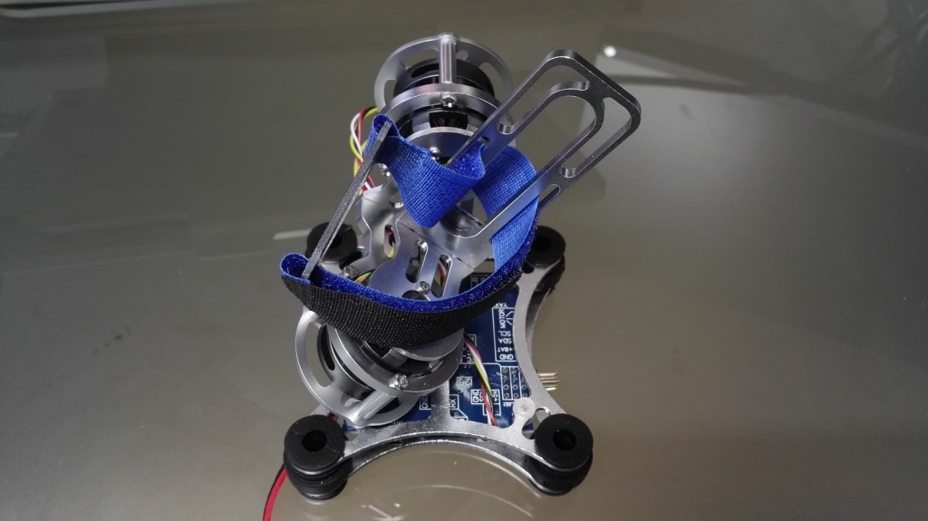
So, is it any good? Read more...
-
Using transistors as switches
I think all popular computerized DIY devices like Arduino, Raspberry Pi or any other microprocessor/microcontroller based boards has one common drawback: low output current. Few miliamps per pin. While this is enough to light a single LED or provide input to other electronics device, it is far from enough to run a motor or power a LED strip. It's all about current.
Good thing this problem can be solved with two additional devices: resistor and bipolar transistor. Together they can act as a switch. Idea is simple: low current (and voltage if you wish) applied to transistor base causes bigger current (and voltage) to be passed between collector and emmiter. We have two choices: NPN or PNP bipolar transistor. Switch that uses NPN transistor is open/enabled when positive voltage is applied to base. In other words, base is connected to plus.


I'm Paweł Spychalski and I do things. Mainly software development, FPV drones and amateur cinematography. Here are my YouTube channels: