How to use stepper motors with Arduino
Stepper motors are the workhorse of modern automation and mechatronics. You want something to more and move precisely how much wanted it to move? You use a stepper motor. This is why, we use steppers in cars, robots, all kinds of automation, 3D printers, CNC machines. You name it.
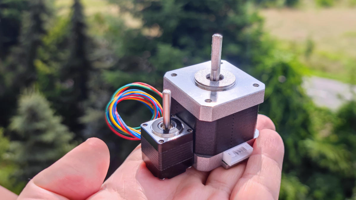
The main difference between a stepper motor and any other electric motor is that the stepper, when electricity moves through its coils, will rotate the shaft only by a defined angle, one step. If you want it to move another “step”, you have to energize the coils in a different way. The step is constant for the motor. For example, a motor with 100 steps per resolution, will always move 3.6 degrees per one full step. Motor with 200 steps per revolution will move 1.8 degrees per step and so on.
To use steppers, you need a driver called a stepstick. The most popular are TCM2209, DRV8825, or A4988. They are all-in-one stepper motor controllers. You connect stepper coils, voltage, control signal and done! The driver will take care of how and when to energize each coil. More than that, modern stepstick can do something called “microstepping”. They can divide one step into smaller steps by precisely controlling magnetic fields. For example, with 1:8 microstepping, 100 steps-per-revolution motor has now 800 steps and each step is only 0,45 degrees. The price to pay is smaller torque, but extra precision is often more important than torque.
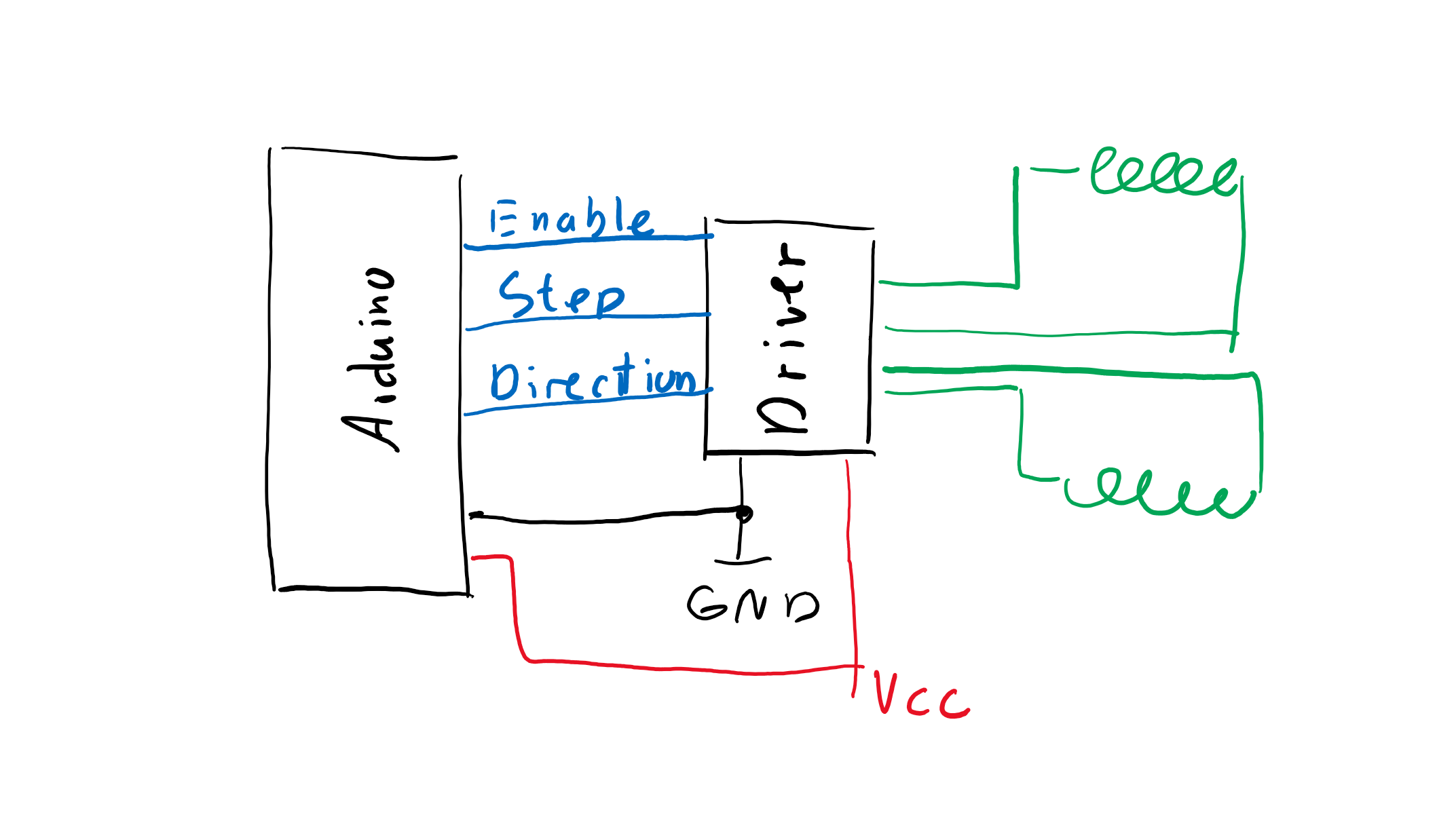
Almost all stepper motor drivers use a “standard” protocol for controlling the motors. It uses 3 pins:
- ENABLE - the driver will work only when ENABLE pin is, depending on the driver, pulled LOW or HIGH
- DIRECTION - when LOW, the motor will rotate in one direction, when HIGH in the other direction. It’s relative to the way you connected the motor!
- STEP - Every time STEP pin goes from LOW to HIGH, the stepper will make one step (or microstep, depending on the driver settings).
Example
In this example, TCM2209 stepstick is connected to ESP32 and we use the most simple way of controlling it. No timers, no interrupts, just a fully manual control
- ENABLE pin goes to ESP32 GPIO 14
- DIRECTION pin goes to ESP32 GPIO 13
- STEP pin goes to ESP32 GPIO 12
Motor rotation is controlled with variable stepsPerSecond. If it’s greater than 0, motor will rotate one direction, if it’s lower than 0, it will rotate in the other direction.
//Stepper driver pin definitions
#define PIN_STEP_ENABLE 14
#define PIN_STEP1_DIRECTION 13
#define PIN_STEP1_STEP 12

//Button pin definitions
#define PIN_BUTTON_1 21
#define PIN_BUTTON_2 22

//Stepper driver variables
int stepsPerSecond = 0;
int currentPosition = 0;

void setup()
{
    //Set both buttons as INPUT_PULLUP so we can detect when they are pressed
    pinMode(PIN_BUTTON_1, INPUT_PULLUP);
    pinMode(PIN_BUTTON_2, INPUT_PULLUP);

    //Condifure stepper driver pins as OUTPUTs
    pinMode(PIN_STEP1_DIRECTION, OUTPUT);
    pinMode(PIN_STEP1_STEP, OUTPUT);
    pinMode(PIN_STEP_ENABLE, OUTPUT);

    //ENABLE pin has to be pulled LOW for TCM2209 used in this example to enable the driver
    digitalWrite(PIN_STEP_ENABLE, LOW);
}

void loop()
{
    //Check if the button is pressed
    if (digitalRead(PIN_BUTTON_1) == LOW) {
        //Forward direction
        stepsPerSecond = 5000;
    } else if (digitalRead(PIN_BUTTON_2) == LOW) {
        //Backward direction
        stepsPerSecond = -5000;
    } else {
        //If non of the buttons is pressed, set stepsPerSecond to 0
        stepsPerSecond = 0;
    }

    static unsigned long nextChange = 0;
    static uint8_t currentState = LOW;
    if (stepsPerSecond == 0)
    {
        //if speed is 0, set the step pin to LOW to keep current position
        currentState = LOW;
        digitalWrite(PIN_STEP1_STEP, LOW);
    }
    else
    {
        //if stepsPerSecond is not 0, then we need to calculate the next time to change the state of the driver
        if (micros() > nextChange)
        {

            //Generate steps
            if (currentState == LOW)
            {
                currentState = HIGH;
                nextChange = micros() + 30;

                if (stepsPerSecond > 0)
                {
                    currentPosition++;
                }
                else if (stepsPerSecond < 0)
                {
                    currentPosition--;
                }
            }
            else
            {
                currentState = LOW;
                nextChange = micros() + (1000 * abs(1000.0f / stepsPerSecond)) - 30;
            }

            //Set direction based on the sign of stepsPerSecond
            if (stepsPerSecond > 0)
            {
                digitalWrite(PIN_STEP1_DIRECTION, LOW);
            }
            else
            {
                digitalWrite(PIN_STEP1_DIRECTION, HIGH);
            }

            //Write out the step pin
            digitalWrite(PIN_STEP1_STEP, currentState);
        }
    }
}
The code is also available on GitHub and as a video tutorial on my YouTube channel.

I'm Paweł Spychalski and I do things. Mainly software development, FPV drones and amateur cinematography. Here are my YouTube channels: