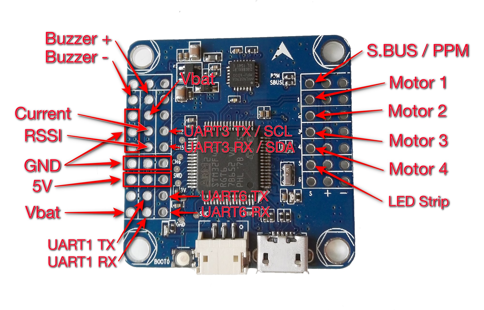
There is very little reliable information about Flip32 F4 / Airbot F4 on the internet, so I’ve decided to fix it. Today, pinout map for Flip32 F4 (Betaflight 3.0.1) and some additional notes:
- Betaflight 3: use REVO target
- UART1 is only UART with inverters, so S.BUS can be connected only here
- S.BUS / PPM pin is connected to UART1 RX
- To use PPM, UART1 can not be used
- To use S.Bus, UART1 has to be used as SerialRx
- FrSky S.Port can be used only with UART1 (inverters)
- UART3 is shared with I2C. I2C can not be used when UART3 is enabled
- external I2C is not tested ATM
- Both Vbat lines are connected to onboard 1.5A voltage regulator (BEC)
- Onboard BEC has to be powered if voltage monitoring is used
- Onboard BEC will be disabled only if voltage supplied to ESC lines is higher than BEC output! This is a design flaw! There is no way to force usage of external BEC and still use voltage monitoring!
- I suggest not to supply 5V to OSD from UART header but use external BEC with common ground
a uart1,uart3,and uart6 are shown. are the uart2 & uart4 on the bottom of the board, or does the board just have the 3 uarts?
Russ from Coral Springs, Fl. usa
Only 3 UARTs are available: 1 3 and 6. Those are STM32F4 hardware names for used UARTs
Great, this is helpful. Can this target be used with iNav?
In theory yes, but not everything will work. I will have to update INAV target to enable all features
Thanks for this… why doesn’t any FPV components come with at least a web link to even a basic wire hookup diagram? Please continue, we need this!
Hi could you tell me please where to connect the signal wire of my spektrum satelite to when i want to bind it? Is it UART3 (RX) / TX / SBUS … ? I just cant get it to bind correctly using raceflight (with serial_rx on uart3, spektrum 2048 and “set spektrum_sat_bind = 9”).
Hi,
According to Betaflight 3.0.1 it should be UART3 RX pin. But never tested myself
UART3 worked for me, but only using betaflight instead of raceflight. Thank you!
Since Raceflight is no longer OpenSource I can not help you with that…
Lars
It’s always easier To bind your satalite using another receiver then once it’s bound connect that to your FC and your ready to go. Going through the FC to bind is a pain I think.
Spektrum sat connects to J8 which is the socket next to the micro USB socket, you can either plug the sat lead straight in (shortened to suit) or as I did solder to the rear of the socket. You will then be able to bind with the CLI
I soldered the pins to uart one but every time I try to save and reboot the board connects it then says there was no connection for 10 seconds and disconnects and when I plug and unplug serial rx is back off.
PLEASE HELP
In rcgroups, one user mentioned that the FC regulator gets very hot if battery voltage is connected to VBAT. What’s the best way of powering the FC and keep voltage monitoring alive, but not risk overheating at the same time?
And did I get you right: If I connect 5 Volt from external BEC to a FC ESC pin, voltage monitoring will be dead? So we should connect full LiPo voltage (4S in my case) to the VBAT pin and we are good to go? No risk of thermal runaway of the regulator?
LDO getting hot only when too much current is drawn from it. ATM I’m powering FC itself and X4RSB from the board.
Only OSD is powered from secondary BEC and 5V from that BEC is not connected to +5V ESC pins.
Great news, thank you! I’ll power VTX and camera from my MATEK board BECs separately and not connect the MATEK +5V to the FC’s ESC pins.
Hi,
thanks for your great post – helped me a lot. Currently I’m stuck in getting my X4R frsky receiver to work. I soldered it to 5V,GND,SBUS (above the ESC signal PINs). Is this the correct position? It didn’t work for me. In Betaflight I configured UART1 as serial_RX.
Should I solder the PINs from X4R receiver to UART1 RX pin?
Thanks for your help!
Yes, those are correct pins. Check if SBUS protocol is used . UART1 should be serialRX and SerialRX should be chosen on “configuration” screen
Thanks for your quick response. Of course I also choose serial rx in the configuration screen. Still no success. I’m using betaflight 3.1.0. Maybe I try to downgrade.
I was able to use it on Betaflight 3.0 and 3.0.1 as well as INAV without problems
Thanks for your help. I figured out the issue. The flight controller was simply damaged. Luckily I had a second one and there it works like a charm – also with Betaflight 3.1.0.
Finally I finished my quad.
Thanks for your help!
cAN SOMONE PLEASE HELP HE WIRING MY FLYSKY PPM RX
Do you think just removing the voltage regulator and adding 5v to the ESC line would allow the FC to operate correctly and stop the heating issue?
There are reports that LDO removal can cause gyro problems. So both removal and bridge from 5V rail to LDO output is required
So if I remove the reg and bridge between the output pad (5v) and the esc rail 5v all should be OK?
When I only connected via 5v from PDB to ESC pins my airbotF4 didn’t work properly. When I connected to VBAT on the flight controller with full voltage it was fine. Now I have both connected and it works as expected. In rcgroups there was the recommendation to connect both. But I have a clone from banggood, maybe there is a difference.
Yeah I have both connected but it’s such a tight build it’s overheating.
I have both PDB 5v and FC reg running with vbat (4S). Still gets very hot. No other load. Interested to see what the solution is.
Is there a possibility to get telemetry working? Tried UART1 Tx, didnt work. I also tried UART6 TX and UART6 TX with a bridge to RX and softserial enabled. no luck. i also tried telemetry_inversion ON but also no luck. this is frustrating 🙁
Hi!
yes, I got it working. Both should work UART1 TX or UART6 TX. I got soldered it to UART6 TX. I have a X4R-SB receiver. There is a trick to solder the telemetry wire on the X4R-SB to a certain position (see: https://blck.mn/2016/06/smartport-the-frsky-xsr-and-betaflight/ -> last picture, green arrow). This wire you connect then to UART TX.
Hope that helps.
Which telemetry protocol and which software. I’m using INAV with SmartPort ion this board with external hardware inverters without any problems
I read all the comment here and am still confused. Could anyone check if I understand correctly:
1. I want to have voltage monitoring working.
1) Do connect Lipo battery input on PDB to VBAT on FC.
2) Do not connect 5V on PDB to ESC pins on FC.
2. There are two VBAT pins. Which one should I connect from PDB? Which GND should be connected for VBAT?
I am using Flip32 F4 MPU6500 version and Matek 5 in 1 PDB.
Both VBAT are the same line, so you can choose freely.
Voltage Monitoring will work only with VBAT connected. I suggest to connect VBAT, but power RX from PDB
Only connecting from PDB to VBAT can supply power to FC?
and also any GND can be used for VBAT? I mean + for VBAT pin and – for any GND?
Yes, directly from battery to VBAT and it will power FC.
GND from PDB and FC have to be connected, but this is all.
See https://youtu.be/CevrAEFfdog
Thank you. it is helpful very much!
I’m wondering if there’s a way to use flysky pwm rx? I see a ch5 and ch6 but where is 1-4? This is my first flight controller after the Naze32. I’m getting a trannis in the future so would I have to get that first?
In theory it is possible to use pins from UARTs and I2C as PWM, but that does not makes much sense.
You can buy FlySky iA6B to get PPM from it
Hello ! Is it possible to input 5s voltage to the vbat ? Or will it fry the sensor ?
Onboard voltage stabilizer will will overheat. It can barely stand 4S. So I would say, no, do not connect 5S to Vbat to this board
Even if i dont pull any current from it ? I mean my pdb supplies 5v to my camera, receiver, and to the card via esc rails ?
Thanks
This board has poor ESC rail separation. Even if powering only board itself, it will overheat.
21V-5V = 16V. 16V * 100mA = 1.6W of heat.
You can try removing LDO and making a passthrough from ESC rail to LDO output.
What is the current pinout use for? And how to wire it up?